CANバス
このチュートリアルでは、Aotenjo One ボードを CAN バス通信用に準備し、閉ループ角度制御を実行する方法を検討します。
Aotenjo One V2.x と Aotenjo Master v2.x の両方をお持ちの場合は、代わりに CAN FD 通信チュートリアル] を参照してください。
AotenjoでCANバスを使用する理由
1 台の Aotenjo Master ボードで複数の Aotenjo One ボードを制御する場合は、Aotenjo ボードとの CAN バス通信を使用することをお勧めします。 Aotenjo で CAN Bus を使用する利点の詳細については、Aotenjo Master CAN Bus チュートリアル] を参照してください。
前提条件
このチュートリアルでは、次のハードウェアが使用されます。
- Aotenjo Oneボード MCU: STM32G431CBU6 バージョン: Aotenjo One V1.4
- 直径方向着磁ディスクマグネット(Aotenjo Oneに付属)
- ST-LINK V2 クローン
- BlackPill STM32 ボード
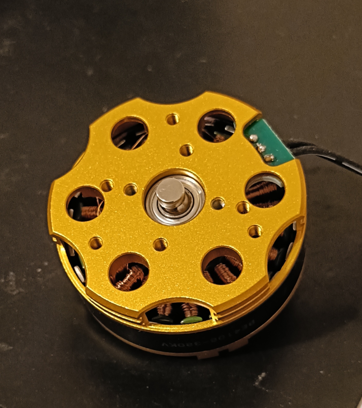
- BE4108 75T ジンバルモーター
- 電源(12V)
- はんだ付けキット
ファームウェアをボードにアップロードするには、ST-LINK V2 クローンが必要です。安価なクローン ST-LINK V2 は 5 ドル以下で購入できます。
CANバス接続
Aotenjo One は CAN バス経由で通信するため、CAN_H、CAN_L、VCC、GND の 4 本のワイヤだけを使用して複数の Aotenjo One ボードを制御できます。
CAN バスでは、信号の反射を防ぐためにネットワークの両端に 終端抵抗 が必要であることに注意してください。

上に示したセットアップでは、メイン CAN ハブ (Aotenjo Master) に終端抵抗が組み込まれています。したがって、以下の図に示すように、ボードの上面にある終端ジャンパーをはんだ付けすることによって、チェーン内の最後の Aotenjo One ボード (M0 ユニットなど) で終端を有効にするだけで済みます。

インストール
VScode と PlatformIO
PlatformIO は、VSCode 拡張機能マーケットプレイスからインストールできます。
STM32CubeProgrammer
これはファームウェアをボードにフラッシュするために必要です。
クローンを作成 リポジトリ
git clone https://github.com/aotenjo-xyz/one.git
cd one
git checkout v1.0
クイックスタート
- モーターのシャフトに磁石を置きます。
-
Aotenjo One ボードを ST-LINK V2 プログラマに接続します。
 ST-LINK V2 <-> Aotenjo One3.3V <---> 3.3VGND <---> GNDSWDIO <---> SWDIOSWCLK <---> SWCLKRST <---> NRST備考
blackpill ボードとは異なり、NRST ピンを STM32G4 シリーズの ST-LINK V2 プログラマに接続する必要があります。
あるいは、アップロード中に Aotenjo One ボードの NRST ボタンを押し続けると、同じ効果が得られます。
:::
3. ST-LINK V2 プログラマをコンピュータに接続します。
4. VSCode でプロジェクト フォルダーを開きます。
5. 左側のサイドバーの「PlatformIO」タブをクリックし、「Upload」ボタンをクリックしてファームウェアをボードにアップロードします。

これで、CAN バス通信を使用してモーターを制御する準備が整いました。
次の手順については、Aotenjo Masterボード CAN Bus チュートリアル] を参照してください。