CAN Bus
In this tutorial, we will explore how to prepare the Aotenjo One board for CAN Bus communication and run closed loop angle control.
If you have both Aotenjo One V2.x and Aotenjo Master v2.x, please refer to the CAN FD Communication tutorial instead.
Why Use CAN Bus with Aotenjo?
We recommend using CAN Bus communication with Aotenjo boards when you want to control multiple Aotenjo One boards using a single Aotenjo Master board. Please refer to the Aotenjo Master CAN Bus tutorial for more details on the advantages of using CAN Bus with Aotenjo.
Prerequisites
In this tutorial, the following hardware is used:
- Aotenjo One Board
MCU: STM32G431CBU6
Version: Aotenjo One V1.4 - Diametrically magnetized disc magnet (included with Aotenjo One)
- ST-LINK V2 Clone
- BlackPill STM32 Board
- BE4108 75T Gimbal Motor
- Power Supply (12V)
- Soldering Kit
You need a ST-LINK V2 Clone to upload the firmware to the board. You can purchase a cheap clone ST-LINK V2 under $5.
CAN Bus Connection
Connect the boards in a daisy chain using CAN_H and CAN_L for communication, and VCC and GND for power and a shared ground reference.
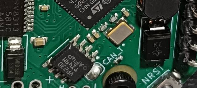
The CAN bus requires a 120 Ω termination resistor across CAN_H and CAN_L at each physical end to reduce signal reflections. Do not enable termination on boards in the middle of the bus. The diagram below shows the CAN signal wiring; power and ground wiring are omitted.

Use the termination method provided on your board:
- Boards with a solder jumper: Bridge the termination jumper pads with solder when the board is at a physical end of the bus. Leave the pads unbridged, or remove the solder bridge, when the board is in the middle.
- Boards with a CAN termination switch: Set CAN TERM to ON when the board is at a physical end of the bus, or OFF when it is in the middle.

Example: Winding Machine
Our winding machine uses the following daisy-chain arrangement. The order represents the physical connections, not the direction of communication:
Aotenjo Master — Aotenjo One (M3) — Aotenjo One (M2) — Aotenjo One (M1) — Aotenjo One (M0)

In this setup, Aotenjo Master v2.1 provides built-in termination at one end of the bus. Enable termination on Aotenjo One M0 at the other end, using its solder jumper or CAN termination switch. Leave termination disabled on M1, M2, and M3.
If you use a Master board with a CAN termination switch in this same position, set its switch to ON as well.
Installation
VScode with PlatformIO
You can install PlatformIO from the VSCode extension marketplace.
STM32CubeProgrammer
You need this to flash the firmware to the board.
Clone the repository
git clone https://github.com/aotenjo-xyz/one.git
cd one
git checkout v1.0
Quickstart
-
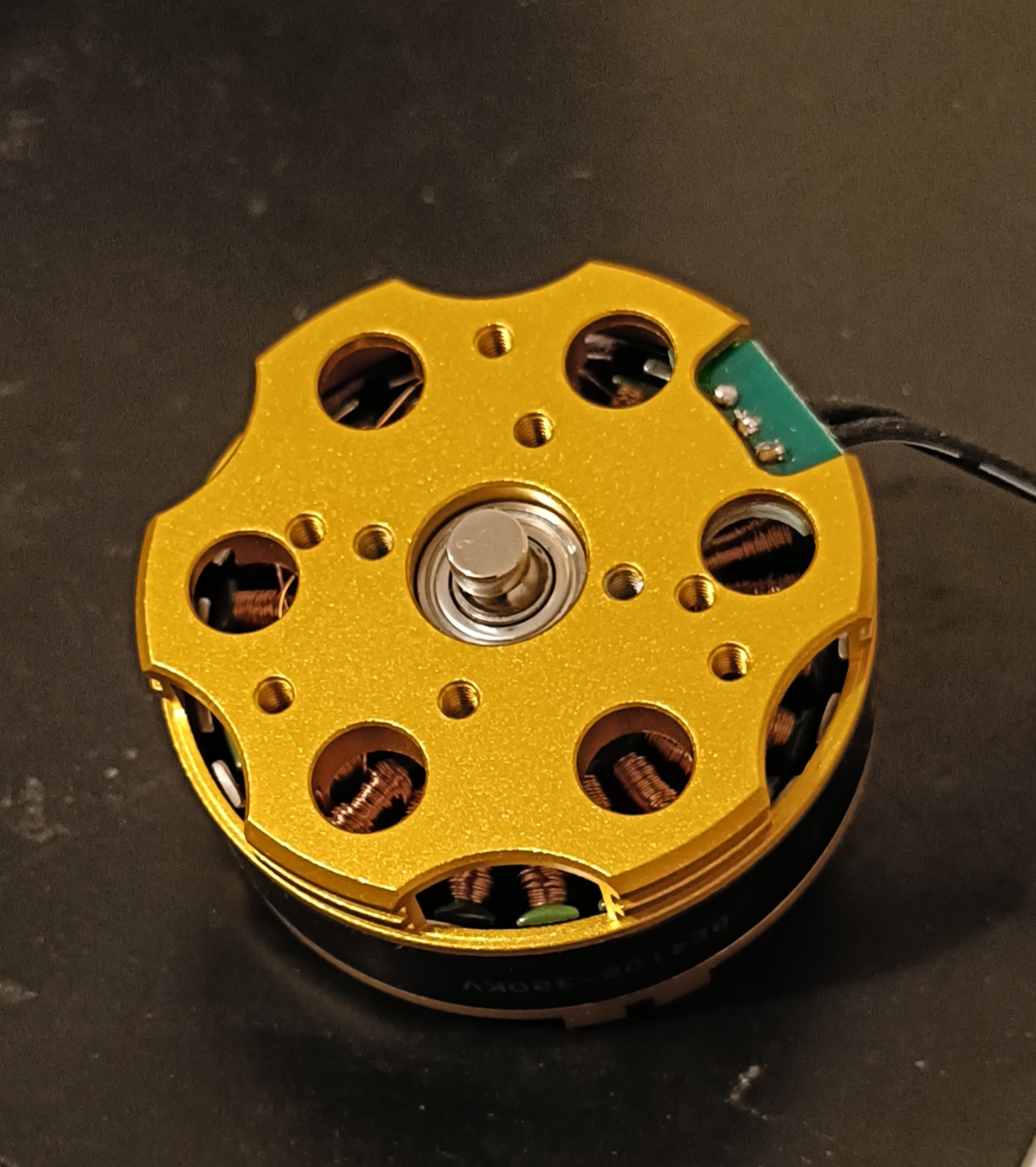
Place the magnet on the motor shaft.
-
Connect the Aotenjo One board to the ST-LINK V2 programmer.
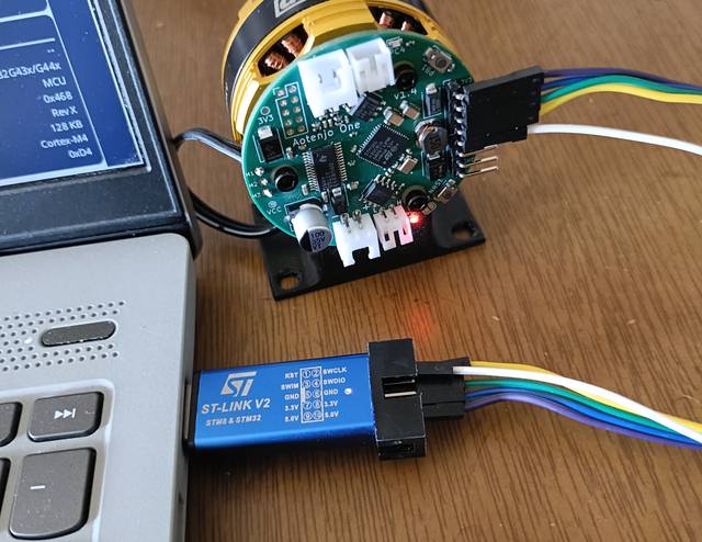 ST-LINK V2 <-> Aotenjo One3.3V <---> 3.3VGND <---> GNDSWDIO <---> SWDIOSWCLK <---> SWCLKRST <---> NRSTinfo
Unlike the blackpill board, you need to connect the NRST pin to the ST-LINK V2 programmer for STM32G4 series. Alternatively, you can press and hold the NRST button on the Aotenjo One board during the upload process to achieve the same effect.
-
Connect the ST-LINK V2 programmer to your computer.
-
Open the project folder in VSCode.
-
Click on the PlatformIO tab on the left sidebar and click on the
Uploadbutton to upload the firmware to the board.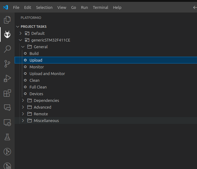
Now you are ready to control the motor using CAN Bus communication!
For the next steps, please refer to the Aotenjo Master CAN Bus tutorial.