Rewinding the Eaglepower LA8308

We are prototyping a high-torque, low-speed version of the Eaglepower LA8308 motor by rewinding it with 0.29 mm enameled copper wire and 70 turns.
In this test, we compare the new 0.29 mm / 70-turn winding with our previous 0.30 mm / 60-turn version. The goal is to increase the motor's torque constant while keeping the current requirement suitable for our motor controller.
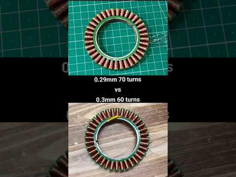
Eaglepower LA8308 0.3mm 60T vs 0.29mm 70T
Reason for rewinding
We are developing a new, larger winding machine called Winder Max, designed to support stators up to 150 mm in outer diameter and 100 mm in thickness.
This machine is intended for larger motors used in applications such as e-scooters, e-bikes, hoverboards, and other high-torque systems.
Our current winding machine supports stators up to 90 mm in outer diameter and 15 mm in thickness. Because Winder Max is significantly larger and must handle much heavier stators, it requires a more powerful M2 motor than the BE4108 75T used in our current machine.
For this reason, we decided to rewind the Eaglepower LA8308 and use it as the M2 motor for Winder Max. The original LA8308 is a low-KV drone motor designed to produce high power at relatively high current. By replacing its original winding with many more turns of thinner wire, we can convert it into a high-resistance, high-torque-constant motor better suited to low-speed direct-drive operation.
In other words, we are converting a drone motor into a direct-drive motor for our winding machines.
References:
0.3mm / 60T
We then rewound the LA8308 with 0.29 mm wire and 70 turns.
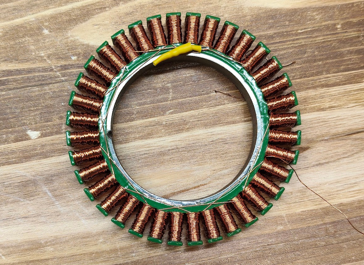
As shown above, some unused space remained in each stator slot. This suggested that we could fit more turns by using slightly thinner wire.
Increasing the number of turns generally increases the motor's torque constant, allowing it to produce more torque per ampere. Therefore, we decided to try 0.29 mm wire with 70 turns.
Another consideration was winding resistance. The 0.30 mm / 60T motor measured approximately 9.8 Ω line-to-line, which is slightly lower than our target for the Aotenjo One BLDC motor controller.
For this application, we target a motor winding resistance of approximately 10 Ω or higher.
0.29mm / 70T
We rewound the motor with 0.29mm wire and 70 turns.
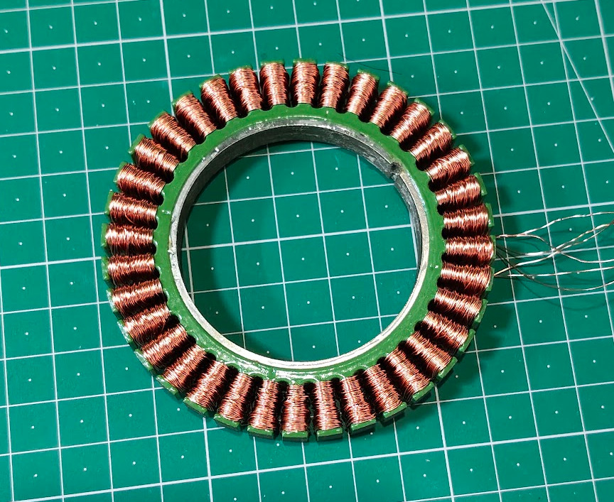
The additional turns use the available slot space much more effectively. At 70 turns, the winding is already very tight, and increasing the number of turns further would make the winding considerably more difficult and less repeatable.
As the slots fill, the wire becomes more likely to get caught or cross incorrectly, making it difficult to reach the target number of turns without damaging the winding.
The finished motor measured approximately 13.4 Ω line-to-line, giving us comfortable resistance margin for use with the Aotenjo One BLDC motor controller.
For our winding process, 0.29 mm / 70T appears to be a good balance between turn count, slot utilization, winding resistance, and manufacturing reliability.
Why We Compare Torque at Similar Current Instead of Voltage
The two motors have different winding resistances, so applying the same voltage does not result in the same current.
The 0.29 mm / 70T winding has a higher resistance than the 0.30 mm / 60T winding. At the same supply voltage, it therefore draws less current.
For a BLDC motor, torque is approximately proportional to the torque-producing current:
Torque = Kt × Iq
where:
- Torque is the motor torque
- Kt is the motor torque constant
- Iq is the torque-producing current
Increasing the number of turns generally increases (K_t). Therefore, when comparing two winding configurations, comparing their torque at similar current gives us more information about how the winding change affects torque production than simply applying the same voltage to both motors.
However, there is an important limitation to our test: the current displayed by the laboratory power supply is DC input current to the motor controller, not a direct measurement of motor phase current or (I_q).
Therefore, this should not be considered a precise measurement of the motor's torque constant. Instead, it is a practical comparison using the same controller and test setup.
Torque Comparison
For this test, we attached a flange with a 10 mm effective radius to the motor shaft. A polyester rope connected the flange to a force gauge.
The motor was operated using closed-loop angle control. As the motor attempted to reach its target angle, it pulled against the force gauge.
The laboratory power supply displayed the input voltage, current, and electrical power in real time.
Here is the torque test:
The measured results were:
| Winding | Supply Voltage | Input Current | Input Power | Measured Torque |
|---|---|---|---|---|
| 0.30 mm / 60T | 20.58 V* | 2.50 A | 51.42 W | 11.87 kgf·cm |
| 0.29 mm / 70T | 24.0 V | 1.80 A | 43.21 W | 11.8 kgf·cm |
| 0.29 mm / 70T | 28.0 V | 2.02 A | 56.51 W | 13.5 kgf·cm |
| 0.29 mm / 70T | 32.0 V | 2.235 A | 71.45 W | 14.7 kgf·cm |
*The power supply was set to 24 V, but the 0.30 mm / 60T motor reached the 2.5 A current limit. The supply therefore reduced its output voltage to approximately 20.58 V.
The 0.29 mm / 70T motor produced approximately 11.8 kgf·cm at only 1.8 A of DC input current, while the 0.30 mm / 60T version produced approximately 11.87 kgf·cm while the power supply was already at its 2.5 A current limit.
When the supply voltage for the 70T motor was increased, the controller could draw more current and the measured torque increased further, reaching approximately 14.7 kgf·cm (1.44 N·m) at 32 V and 2.235 A input.
These results suggest that the 70-turn winding is better suited to our low-speed, high-torque application.
This is not a precision torque or motor-efficiency test.
The force gauge, rope, flange, power supply, motor controller, and mechanical setup all introduce measurement uncertainty. In addition, the current shown by the power supply is DC input current rather than measured motor phase current.
The purpose of this experiment is to make a practical comparison between the two winding configurations under the same test setup. The measurements are sufficiently repeatable for us to observe the difference between the two prototypes, but they should not be interpreted as laboratory-grade motor specifications.
We Will Start Selling the Eaglepower LA8308 0.29 mm / 70T
We are happy with the performance of the 0.29 mm / 70T version.
It achieves approximately 13.4 Ω line-to-line resistance, fills the available stator slot space effectively, and provides higher torque at relatively low current compared with our previous 60-turn prototype.
We therefore plan to use 0.29 mm / 70T as the winding configuration for our converted Eaglepower LA8308 motors and will begin offering these motors soon.
The same motor will also be used in our upcoming Winder Max as a high-torque direct-drive motor.