CAN Bus
In this tutorial, we will explore how to control the Aotenjo One board via CAN Bus and run closed loop angle control.
If you haven't set up the CAN Bus yet, please refer to the Aotenjo One CAN Bus tutorial for detailed instructions on wiring and configuration.
What is CAN Bus?
CAN Bus (Controller Area Network) is a robust vehicle bus standard designed to allow microcontrollers and devices to communicate with each other without a host computer. It is widely used in automotive and industrial applications due to its reliability and efficiency.
Why Use CAN Bus with Aotenjo?
Using CAN Bus with Aotenjo boards offers several advantages:
- Robust Communication: CAN Bus is designed to handle noisy environments, making it ideal for motor control applications.
- Multi-Device Support: Multiple Aotenjo One boards can be connected to a single Aotenjo Master board, allowing for complex multi-motor setups.
- Real-Time Control: CAN Bus enables real-time communication, essential for precise motor control and feedback.
- Scalability: Easily add more Aotenjo One boards to your system without significant changes to the wiring or software.
- Reduced Wiring Complexity: CAN Bus uses a two-wire differential signaling system, reducing the amount of wiring needed compared to traditional serial communication methods.
Prerequisites
In this tutorial, the following hardware is used:
- Aotenjo One Board
MCU: STM32G431CBU6
Version: Aotenjo One V1.4 - Aotenjo Master Board
MCU: STM32G431CBU6
Version: Aotenjo Master V1.1 - Diametrically magnetized disc magnet (included with Aotenjo One)
- ST-LINK V2 Clone
- BlackPill STM32 Board
- BE4108 75T Gimbal Motor
- Power Supply (12V)
You need a ST-LINK V2 Clone to upload the firmware to the board. You can purchase a cheap clone ST-LINK V2 under $5.
Installation
VScode with PlatformIO
You can install PlatformIO from the VSCode extension marketplace.
STM32CubeProgrammer
You need this to flash the firmware to the board.
Clone the repository
git clone https://github.com/aotenjo-xyz/master.git
cd master
git checkout v1.0
Quickstart
-
Connect the Aotenjo Master board to the ST-LINK V2 programmer.
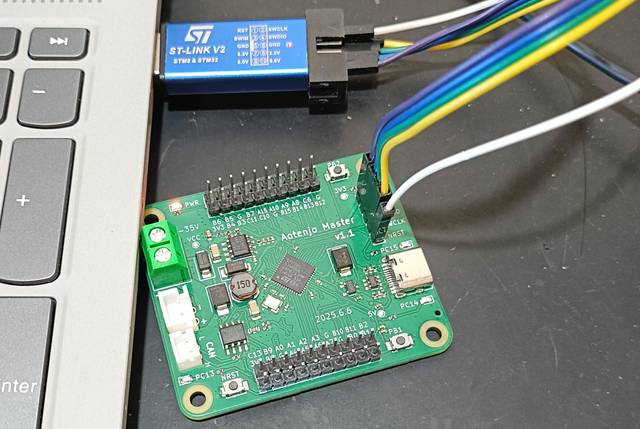 ST-LINK V2 <-> Aotenjo Master3.3V <---> 3.3VGND <---> GNDSWDIO <---> SWDIOSWCLK <---> SWCLKRST <---> NRSTinfo
Unlike the blackpill board, you need to connect the NRST pin to the ST-LINK V2 programmer for STM32G4 series. Alternatively, you can press and hold the NRST button on the Aotenjo Master board during the upload process to achieve the same effect.
-
Connect the ST-LINK V2 programmer to your computer.
-
Open the project folder in VSCode.
-
Click on the PlatformIO tab on the left sidebar and click on the
Uploadbutton to upload the firmware to the board.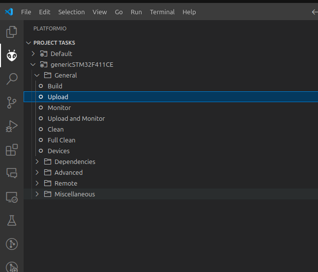
-
Disconnect the ST-LINK V2 programmer, then connect the JST XH cables for power and JST PH cables for CAN Bus between Aotenjo Master and Aotenjo One board/s.
-
Connect the Aotenjo Master board to the computer via USB.
-
Click on the PlatformIO tab on the left sidebar and click on the
Monitorbutton to open the serial monitor.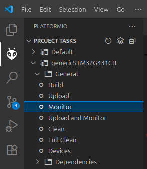
-
Turn on the power supply, and the motor will start rotating to initialize the FOC (Field Oriented Control).
-
Input the following command in the serial monitor and press enter:
M06.28The
M0motor will complete one full rotation and stop at the initial position. You can adjust the target angle by changing the value in radians. You can also rotate the motor in the opposite direction by entering a negative value, such asM0-6.28.To read the current angle of the
M0motor, enter:M0PTo put the motor into sleep mode, use the following command:
ESTOP
This is exactly how our winding machine is controlled using CAN Bus communication with Aotenjo Master and Aotenjo One boards! Hope you enjoy building your projects with Aotenjo!