Closed Loop Angle Control
In this tutorial, we will explore how to run closed loop angle control on the Aotenjo One board.
Prerequisites
In this tutorial, the following hardware is used:
- Aotenjo One Board
MCU: STM32G431CBU6
Version: Aotenjo One V1.4 - Diametrically magnetized disc magnet (included with Aotenjo One)
- ST-LINK V2 Clone
- BlackPill STM32 Board
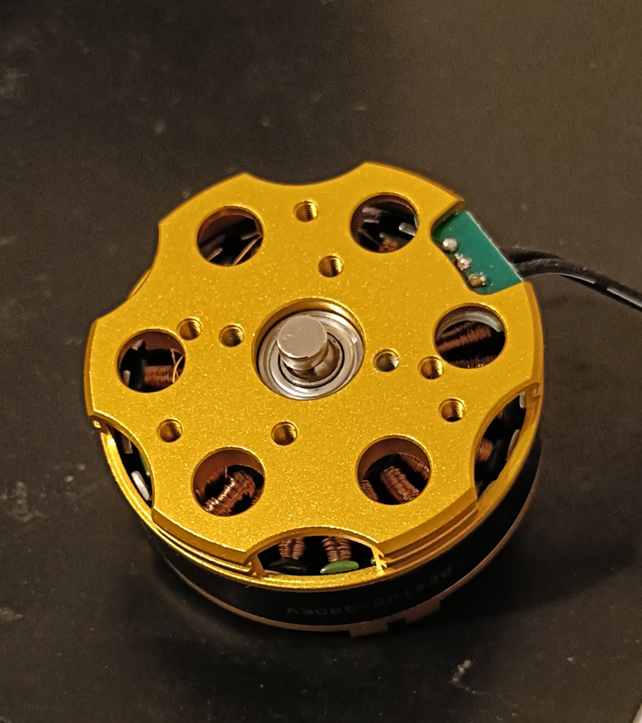
- BE4108 75T Gimbal Motor
- Power Supply (12V)
You need a ST-LINK V2 Clone to upload the firmware to the board. You can purchase a cheap clone ST-LINK V2 under $5.
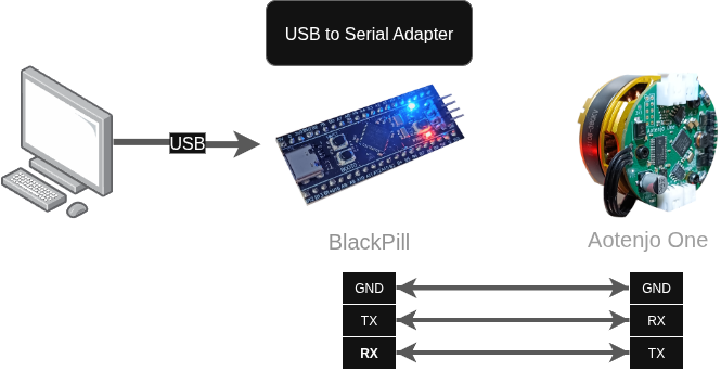
USB to Serial Adapter
Since the Aotenjo One board doesn't have an USB port, you need a USB to Serial adapter to communicate with the board via serial. In this tutorial, we will use a Blackpill STM32 board as a USB to Serial adapter to communicate with the Aotenjo One board, but you can use a cheap USB to Serial adapter or another STM32 board like the Blackpill as an USB to Serial adapter.
You can use the following development boards as a USB to Serial adapter:
- BlackPill STM32 board
- BluePill STM32 board
- ESP32-DevKitC
If you're not sure how to use the BlackPill STM32 board as a USB to Serial adapter, you can refer to the Serial Communication tutorial.
Make sure your BLDC motor's internal resistance is greater than 10 Ω; otherwise, the board may burn out.
Installation
VScode with PlatformIO
You can install PlatformIO from the VSCode extension marketplace.
STM32CubeProgrammer
You need this to flash the firmware to the board.
Clone the repository
git clone https://github.com/aotenjo-xyz/one.git
cd one
The example code for the LED blink is located in the examples/closed_loop_angle_control directory, so run the following command if you use linux or macOS to copy the example code to the src directory:
rm src/*
cp examples/closed_loop_angle_control/main.cpp src/
cp examples/closed_loop_angle_control/platformio.ini platformio.ini
For Windows, you can copy the files manually.
Quickstart
-
Place the magnet on the motor shaft.
-
Connect the Aotenjo One board to the ST-LINK V2 programmer.
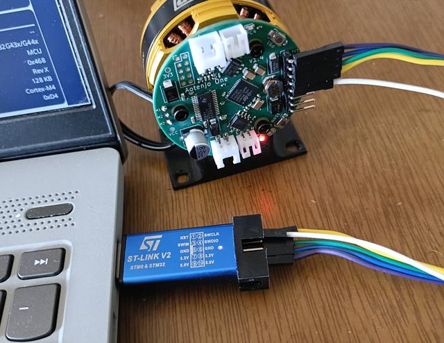 ST-LINK V2 <-> Aotenjo One3.3V <---> 3.3VGND <---> GNDSWDIO <---> SWDIOSWCLK <---> SWCLKRST <---> NRSTinfo
Unlike the blackpill board, you need to connect the NRST pin to the ST-LINK V2 programmer for STM32G4 series. Alternatively, you can press and hold the NRST button on the Aotenjo One board during the upload process to achieve the same effect.
-
Connect the ST-LINK V2 programmer to your computer.
-
Open the project folder in VSCode.
-
Click on the PlatformIO tab on the left sidebar and click on the
Uploadbutton to upload the firmware to the board.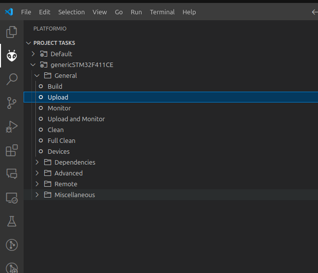
-
Disconnect the ST-LINK V2 programmer, then connect the power supply and the BlackPill STM32 board to the Aotenjo One board. Finally, connect the BlackPill STM32 board to your computer.
Power Supply <-> Aotenjo One12V <---> VCCGND <---> GNDAotenjo One <-> Blackpill STM32TX <---> PA3 (RX)RX <---> PA2 (TX)GND <---> GNDBlackpill STM32 <-> ComputerUSB <---> USB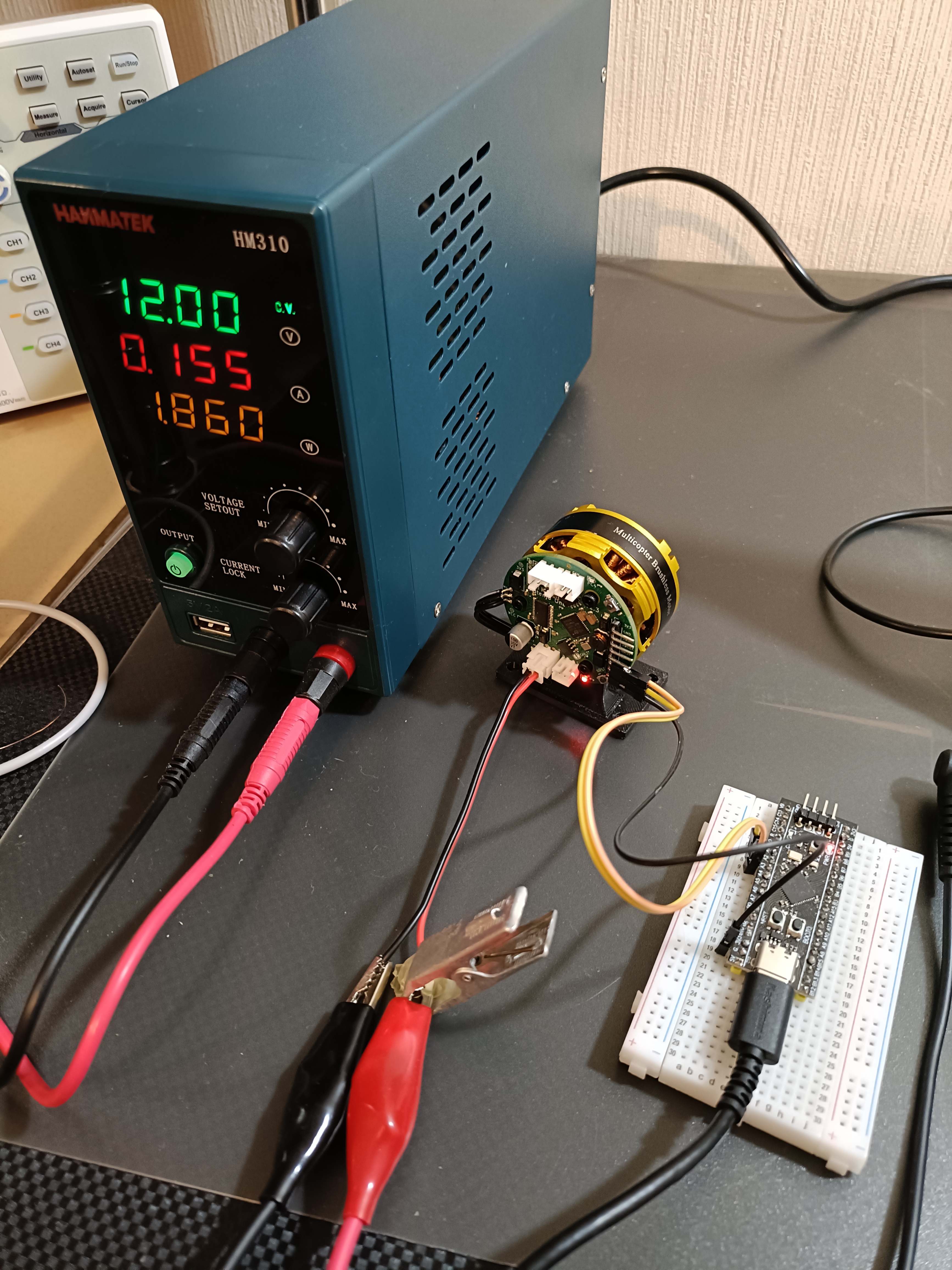
-
Click on the PlatformIO tab on the left sidebar and click on the
Monitorbutton to open the serial monitor.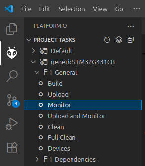
-
Turn on the power supply, and the motor will start rotating to initialize the FOC (Field Oriented Control).
-
Input the following command in the serial monitor and press enter:
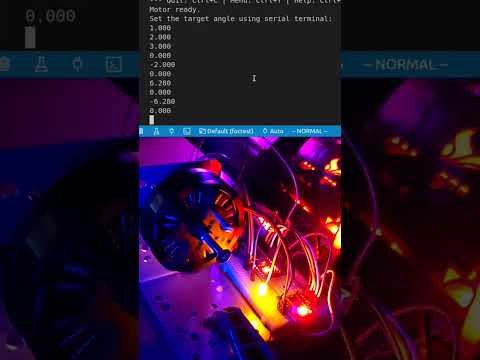
T6.28The motor will complete one full rotation and stop at the initial position. You can adjust the target angle by changing the value in radians. You can also rotate the motor in the opposite direction by entering a negative value, such as
T-6.28.Here is the video demonstration:
Code
Here are the relevant code snippets for the closed-loop angle control implementation:
  // set motion control loop to be used
  motor.controller = MotionControlType::angle;

  // velocity PI controller parameters
  motor.PID_velocity.P = 0.2;
  motor.PID_velocity.I = 20;
  motor.PID_velocity.D = 0.001;
  // maximal voltage to be set to the motor
  motor.voltage_limit = 3.0;

  // velocity low pass filtering time constant
  // the lower the less filtered
  motor.LPF_velocity.Tf = 0.01f;

  // angle P controller
  motor.P_angle.P = 20;
  // maximal velocity of the position control
  motor.velocity_limit = 10;
You can play around with the PID controller parameters to see how they affect the motor's behavior.