Serial Communication
In this tutorial, we will learn how to communicate with the Aotenjo One board using serial communication. This is a fundamental skill for debugging and interacting with your microcontroller projects.
Prerequisites
In this tutorial, the following hardware is used:
- Aotenjo One Board
MCU: STM32G431CBU6
Version: Aotenjo One V1.4 - ST-LINK V2 Clone
- BlackPill STM32 Board
You need a ST-LINK V2 Clone to upload the firmware to the board. You can purchase a cheap clone ST-LINK V2 under $5.
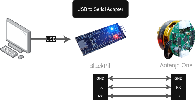
USB to Serial Adapter
Since the Aotenjo One board doesn't have an USB port, you need a USB to Serial adapter to communicate with the board via serial. In this tutorial, we will use a Blackpill STM32 board as a USB to Serial adapter to communicate with the Aotenjo One board, but you can use a cheap USB to Serial adapter or another STM32 board like the Blackpill as an USB to Serial adapter.
You can use the following development boards as a USB to Serial adapter:
- BlackPill STM32 board
- BluePill STM32 board
- ESP32-DevKitC
Installation
We will use the same installation steps as the LED blink example, so please refer to the LED Blink tutorial - Installation for the installation steps.
Quickstart
-
Upload USB to Serial Adapter code to the Blackpill STM32 board.
-
Upload LED Blink code.
-
Disconnect the ST-LINK V2 programmer from the Aotenjo One board.
-
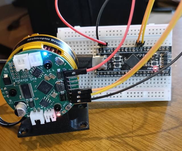
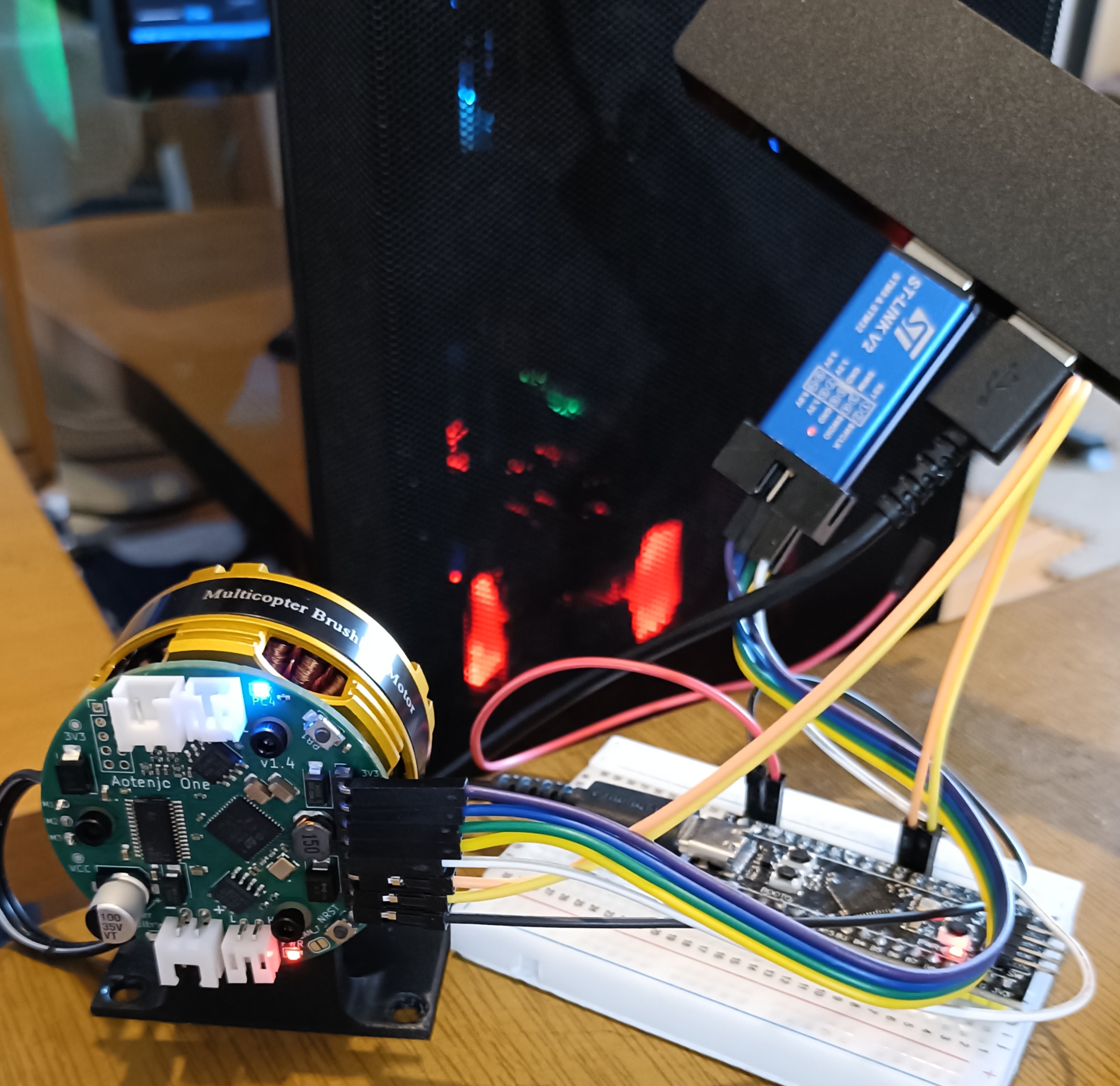
Connect the USB to Serial adapter to the Aotenjo One board as follows:
Aotenjo One <-> Blackpill STM323.3V <---> 3.3VTX <---> PA3 (RX)RX <---> PA2 (TX)GND <---> GNDnoteYou need to connect TX to RX and RX to TX.
-
Connect the USB to Serial adapter to your computer using a USB cable like this:
-
Click on the PlatformIO tab on the left sidebar and click on the
Monitorbutton to open the serial monitor.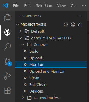
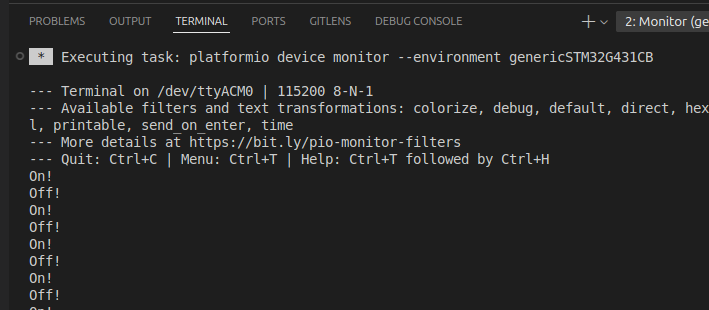
Now you can see the serial output from the Aotenjo One board in the serial monitor.
You can also connect the Aotenjo One board to the ST-Link V2 programmer while using the USB to Serial adapter, so you can debug the code and see the serial output at the same time.
Code
#include <Arduino.h>

HardwareSerial Serial1(PA3, PA2);
Aotenjo One uses Serial1 for serial communication, so you need to use Serial1 instead of Serial in your code.
void setup() {
  Serial1.begin(115200);

  pinMode(LED_PIN, OUTPUT);
  delay(1000);
}

void loop() {
  Serial1.println("On!");
  digitalWrite(LED_PIN, HIGH);
  delay(1000);
  Serial1.println("Off!");
  digitalWrite(LED_PIN, LOW);
  delay(1000);
}
You can use Serial1.println() to send data to the serial monitor. The println() function sends the data followed by a newline character, so you can see the output in the serial monitor.