CAN FD Communication
In this tutorial, we will explore how to prepare the Aotenjo One board for CAN FD communication and run closed loop angle control.
If any board in the CAN network is an Aotenjo One v1.x or Aotenjo Master v1.x, you cannot use CAN FD communication. Please refer to the CAN Bus Communication tutorial instead.
What is CAN FD?
CAN FD (Controller Area Network Flexible Data-Rate) is an extension of the original CAN bus protocol that supports higher data rates and larger data payloads per frame.
Unlike Classic CAN, CAN FD allows:
- A higher bit rate during the data phase of a message
- Up to 64 bytes of payload in a single frame
This makes CAN FD well suited for applications that require high update rates, low latency, and more complex data structures, such as motor control, robotics, and high-performance industrial systems.
Comparison Between CAN and CAN FD
| Feature | CAN Bus | CAN FD |
|---|---|---|
| Maximum Data Rate | Up to 1 Mbps | Up to 8 Mbps(data phase) |
| Data Payload Size | Up to 8 bytes | Up to 64 bytes |
| Frame Format | Standard(11-bit) and Extended(29-bit) | Standard and Extended |
| Error Detection | CRC (Cyclic Redundancy Check) | Enhanced CRC and Bit Stuffing |
| RTR Support | Supported | Not Supported |
| Use Cases | Automotive, Industrial | Automotive, Industrial, High-Speed Control |
Why CAN FD matters for motor control
CAN FD is not just about higher bandwidth.
By allowing larger payloads per frame, CAN FD significantly reduces protocol overhead caused by:
- Arbitration
- Frame headers
- Inter-frame spacing
This means more useful data is transferred per message, improving overall bus efficiency.
Example
With Classic CAN:
- Motor position data may need to be split across multiple frames
- This increases bus load and limits control loop frequency
With CAN FD:
- Position, velocity, current, and status data can be packed into a single frame
- Fewer frames are needed per control cycle
- Higher and more deterministic control loop frequencies become possible
As a result, CAN FD enables:
- Higher update rates
- Lower latency
- Smoother and more responsive motor control
Prerequisites
In this tutorial, the following hardware is used:
- Aotenjo One Board
MCU: STM32G431CBU6
Version: Aotenjo One V2.0 - Diametrically magnetized disc magnet (included with Aotenjo One)
- ST-LINK V2 Clone
- BlackPill STM32 Board
- BE4108 75T Gimbal Motor
- Power Supply (12V)
- Soldering Kit
You need a ST-LINK V2 Clone to upload the firmware to the board. You can purchase a cheap clone ST-LINK V2 under $5.
CAN Bus Connection
CAN FD uses the same bus wiring and termination arrangement as Classical CAN. Follow the CAN bus connection instructions to connect the boards and enable termination at both physical ends of the bus. Then return here to continue with the CAN FD firmware setup.
Installation
VScode with PlatformIO
You can install PlatformIO from the VSCode extension marketplace.
STM32CubeProgrammer
You need this to flash the firmware to the board.
Clone the repository
git clone https://github.com/aotenjo-xyz/one.git
cd one
Quickstart
-
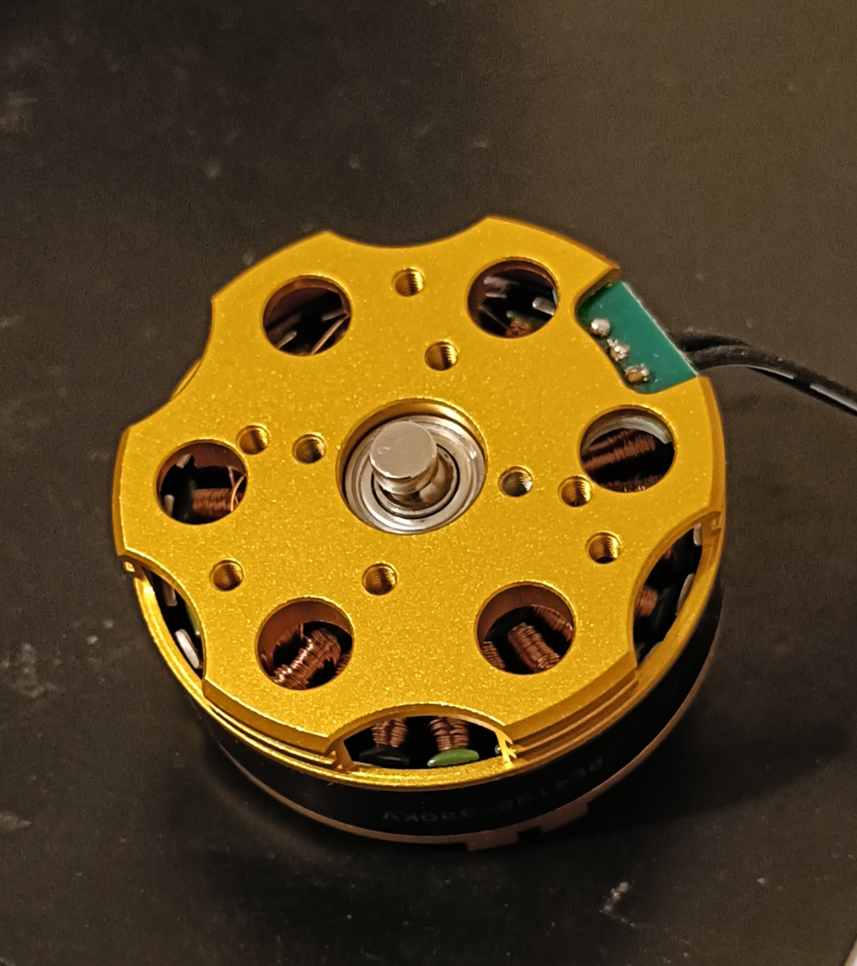
Place the magnet on the motor shaft.
-
Connect the Aotenjo One board to the ST-LINK V2 programmer.
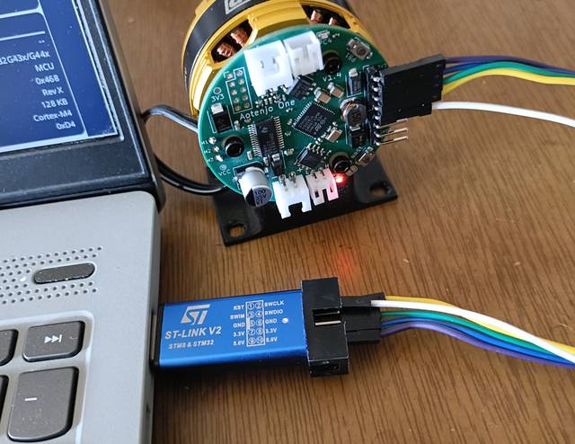 ST-LINK V2 <-> Aotenjo One3.3V <---> 3.3VGND <---> GNDSWDIO <---> SWDIOSWCLK <---> SWCLKRST <---> NRSTinfo
Unlike the blackpill board, you need to connect the NRST pin to the ST-LINK V2 programmer for STM32G4 series. Alternatively, you can press and hold the NRST button on the Aotenjo One board during the upload process to achieve the same effect.
-
Connect the ST-LINK V2 programmer to your computer.
-
Open the project folder in VSCode.
-
Click on the PlatformIO tab on the left sidebar and click on the
Uploadbutton to upload the firmware to the board.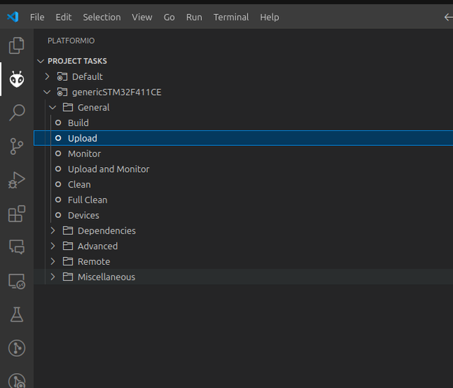
Now you are ready to control the motor using CAN Bus communication!
For the next steps, please refer to the Aotenjo Master CAN FD tutorial.